Share
Pin
Tweet
Send
Share
Send
Another thing is a starter. Power lines go along the smallest path, and control of three thin wires (usually in one cable) goes to the convenient location of the buttons.
Secondly, in addition to the manual control buttons, there may be automatic devices (light, temperature and pressure sensors) that can themselves control the operation of the load.
In addition to the above factors, another advantage of the starter is the switching of a fairly powerful current.
Therefore, it is simply necessary to know how to connect the control buttons to the starter. Yes, on the Internet you can find many electrical circuit diagrams, but how to connect the starter to the “live” circuit, it is not always clear. Even experienced electricians with long experience, without doing this for a long time, may not immediately remember the connection sequence. And what can we say then about a person who does not have a special education.
Next, the article will describe the step-by-step connection of control wires to the starter with explanatory photos.
So, what is needed for this work:
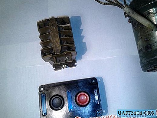
1) unit with two buttons, - power button, - freely open contacts, and disconnect button - freely closed contacts;
2) a starter with a 220 volt coil, and with one additional free open contact;
3) a cable or wire of small cross section in three cores. The cable length is selected depending on where the starter will be, and where the control unit is.
It does not mention the cable or wire that feeds and leaves the load - this is a matter of course.
Now the sequence of work:
1) connect the load wires to the starter. If it is three-phase, then we put one wire on each contact. Well, in the case of a single-phase load, you can connect these three contacts with jumpers and connect a phase load wire to it. This will increase the reliability of the starter, as the current will pass through three contact lines;

2) from the bottom contact of the red button (shutdown), we lead the wire to the starter coil;


3) connect the jumper of the second contact of the red button to the next located contact of the power button. Sometimes such jumpers are already provided by the button manufacturer;

4) we connect the wire from the terminal where the jumper on the "ON" button was set and we lead it to the additional - normally open contact.


By the way, normally open is when the starter is disconnected and the contacts are not connected;
5) from the extreme terminal of the same button, connect the wire to additional contacts on the other hand. In fact, now the ON button is duplicated by these additional contacts;
6) so that the buttons can supply control voltage to the starter coil, at one end we connect the wire to any phase, and the second to the terminal of additional contacts;


7) to the second terminal of the starter coil we connect "ZERO";
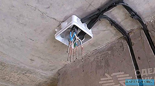
It remains to connect the power supply cable, - in the photo it is in the corrugation, and everything is ready for inclusion.


How the circuit works.
When you press the "START" button, the phase will first pass through the closed contacts through the "STOP" button circuit to the starter coil. So, as there will be zero on the other end of the coil, the electromagnet will retract and the starter contacts will be closed, including additional ones. Since these contacts will be closed by releasing the button, the circuit will not break and the starter will work. Further, by pressing the STOP button, the control phase breaks and the coil is discarded. Accordingly, all contacts open.
That's all. Try it and it will work out.
Share
Pin
Tweet
Send
Share
Send