Share
Pin
Tweet
Send
Share
Send
The proposed device for supplying a digital multimeter from one AA element with a voltage of 1.5 volts will allow to avoid the indicated drawbacks in operation and simplify the operation of the device.

On the Internet there are many different schemes for converting voltage from 1.5 to 9 volts. Each has its pros and cons. This device is made on the basis of A. Chaplygin's circuit published in the journal Radio (11.2001, p. 42).
The difference between this embodiment of the converter is the location of the battery and voltage converter in the cover of the multimeter case, instead of creating a compact power supply installed instead of the Krona battery. This allows you to replace the AA element at any time, without disassembling the device, and, if necessary, disconnect the converter (Jack 3.5 connector) with automatic inclusion of the Krona backup battery located in its compartment. In addition, in the manufacture of a voltage converter, there is no need to miniaturize the product. It is faster and easier to wind the transformer on a larger diameter ring, better heat dissipation, a looser circuit board. This arrangement of nodes in the case cover does not interfere with the multimeter.
This converter can be made in any suitable housing and can be used in a wide variety of devices that require power from a Krona nine-volt battery. These are multimeters, watches, electronic scales and toys, medical devices.
Voltage Converter Generator Circuit
A step-up DC voltage inverter is proposed having good output data with a minimum of input elements. The scheme is shown in the figure.

On transistors VT1 and VT2, a push-pull pulse generator is assembled. The positive feedback current flows through the secondary windings of the transformer T1 and the load connected between the + 9 V circuit and the common wire. Due to the proportional current control of transistors, the losses on their switching have been significantly reduced and the efficiency of the converter has been increased to 80 ... 85%.
Instead of a high-frequency voltage rectifier, base-emitter transitions of the transistors of the generator itself are used. In this case, the magnitude of the base current becomes proportional to the magnitude of the current in the load, which makes the converter very economical.
Another feature of the circuit is the failure of oscillations in the absence of load, which can automatically solve the problem of power management. The current from the battery, in the absence of load, is practically not consumed. The converter will turn on itself when it is required to power something from it and turn off when the load is disconnected.
But since in most modern multimeters the function of automatic power off is introduced, to exclude the refinement of the multimeter circuit, it is easier to install the converter power switch.
Manufacture of voltage transformer
The basis of the pulse generator is a transformer T1.
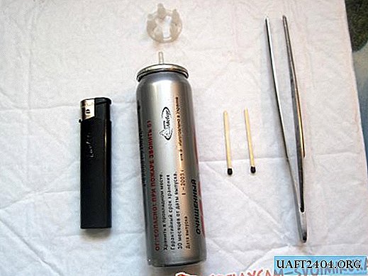
The magnetic core of the transformer T1 is a ring K20x4x4 or K10x4x4.5 of 2000NM ferrite. You can take the ring from the old motherboard.

Transformer winding order.
1. First you need to prepare a ferrite ring.
• In order to prevent the wire from cutting through the insulation strip and damaging its insulation, it is advisable to dull the sharp edges of the ferrite ring with a fine-grained sandpaper or file.
• Wrap the insulating strip on the ring core to prevent damage to the wire insulation. To isolate the ring, you can use varnish, electrical tape, transformer paper, tracing paper, mylar or PTFE tape.

2. Winding of transformer windings with a transformation ratio of 1/7: primary winding - 2x4 turns, secondary winding - 2x28 turns of insulated PEV wire -0.25.
Each pair of windings is wound simultaneously in two wires. Fold in half a wire of measured length and with a folded wire we begin to tightly wind the desired number of turns on the ring.

To avoid damage to the insulation of the wire during operation, if possible, use MGTF wire or another insulated wire with a diameter of 0.2-0.35 mm. This will slightly increase the dimensions of the transformer, will lead to the formation of a second layer of the winding, but will guarantee uninterrupted operation of the voltage converter.
• First, the secondary windings lll and lV (2x28 turns) of the base circuit of the transistors are wound (see the converter circuit).
• Then on the free spot of the ring, also in two wires, the primary windings l and ll (2x4 turns) of the transistor collector circuit are wound.
• As a result, after cutting the loop of the beginning of the winding, each of the windings will have 4 wires - two on each side of the winding. We take the wire of the end of one half of the winding (l) and the wire of the beginning of the second half of the winding (ll) and connect them together. We proceed similarly with the second winding (lll and lV). You should get something like the following: (the red lead is the middle of the lower winding (+), the black lead is the middle of the upper winding (common wire)).

• When winding the windings, the turns can be fixed with glue "BF", "88" or colored tape indicating different colors of the beginning and end of the winding, which will later help to properly assemble the transformer windings.
• When winding all coils, one direction of the winding must be strictly observed, and the beginning and end of the windings must be noted. The beginning of each winding is marked on the diagram with a point at the output. If the phasing of the windings is not observed, the generator will not start, since in this case the conditions necessary for generation will be violated. For the same purpose, as an option, it is possible to use two multi-colored wires from a network cable.
Voltage converter assembly
To work in converters of low power, as in our case, transistors A562, KT208, KT209, KT501, MP20, MP21 are suitable. You may have to choose the number of turns of the secondary winding of the transformer. This is due to the different voltage drop across the p-n junctions for different types of transistors.
Transistors should be selected, focusing on the permissible values of the base current (it should not be less than the load current) and the reverse emitter-base voltage. That is, the maximum allowable base-emitter voltage must exceed the required output voltage of the converter.
In order to reduce interference and stabilize the output voltage, the converter is supplemented with a unit of two electrolytic capacitors (to smooth voltage ripples) and an integral stabilizer 7809 (with a stabilization voltage of 9 volts) according to the scheme:

We assemble the converter according to the scheme and solder all incoming elements on a textolite board cut out from a universal circuit board, sold in radio products, by the method of wall mounting. The dimensions of the board are selected depending on the size of the selected transistors, the resulting transformer and the installation location of the converter. The input, output and common bus of the converter are brought out by a flexible multicore wire. The output wires, with a voltage of + 9V, end with a Jack 3.5 connector for connecting to a multimeter. The input wires are connected to a cassette with a 1.5 volt battery installed.


AA battery (1.5V) is installed in a double cassette from a portable receiver.

One place is occupied by the battery, another place is used to install the power switch and secure the entire cartridge, through the transition textolite strip, in the case of the multimeter.

Converter setting.
We check the correct assembly of the converter, connect the battery and check with the device the presence and magnitude of the voltage at the output of the converter (+ 9V).
If generation does not occur and there is no output voltage, check that all coils are connected correctly. Dots on the converter circuit mark the beginning of each winding. Try to interchange the ends of one of the windings (input or output).
The converter is capable of working even with a decrease in the input voltage to 0.8 - 1.0 volts and to obtain a voltage of 9 volts from one galvanic cell with a voltage of 1.5 V.
Finalization of the multimeter
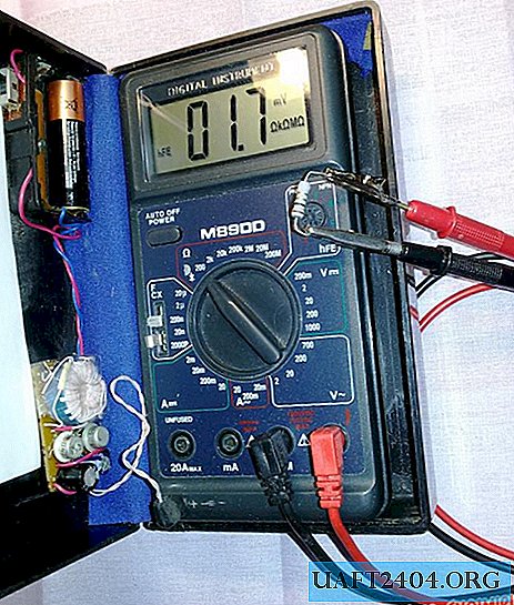
To connect the converter to the multimeter, you need to find free space inside the device and install there a jack for Jack 3.5 or a similar existing connector. In my M890D multimeter, free space was found in the corner to the left of the Krona battery compartment.
As a case for a multimeter, a case from an electric shaver is used.

Prepared by Smirnov I.K.
Share
Pin
Tweet
Send
Share
Send