Share
Pin
Tweet
Send
Share
Send
First you need to deal with the water level diagram, which we will produce.
DIY water level diagram

The first thing, after getting acquainted with the photo: do-it-yourself water level diagram in the tank, is the procurement of parts and materials. We need a ULN2004 chip, you can buy it at a radio store or in China, on Aliexpress. The price for one chip in the radio store and ten for Aliexpress is approximately equal, so choose the right one, the only inconvenience is that you need to wait for a parcel from China for about a month or more.
Details assembled

LEDs can be used with any signal color you like, with a diameter of 4 - 5 millimeters. The pinout of LEDs and microcircuits is on the diagram.
Capacitor C1 needs a polar 100 microfarads of 25 volts, or large parameters (which is).
Resistors (resistances) with power from 0.125 to 0.5 watts or more (the more power, the larger the dimensions and will not be very beautiful, this applies to the capacitor).
Resistors R1 - R7 with a resistance of 47 kΩ (a little less or a little more - not critical).
Resistors R 8 - R14 with a resistance of 1 kΩ (approximately). The greater the resistance, the weaker the LED will glow and vice versa, but too low resistance can lead to failure of the LED.
You can not make a printed circuit board, but use a breadboard, like mine, costs a penny, especially in China. The price ratio in the radio store and China is 5-10 to one.
You can use any eight-wire signal cable to the water level sensors (there are any in the stores that sell alarm devices). The ends of the cable, placed in water as a level sensor, free from insulation to a length of 5 - 10 millimeters and the stripped ends tin (cover with tin using a soldering iron) to reduce the oxidizing effect of water on the metal. A positive electrode must be made of stainless steel (for example, a teaspoon), and the place of its connection to the wire should be protected from water with a glue gun. If the contact point is not protected, then after a short time the electrochemical reaction will gobble up. The step between the sensors must be calculated based on the depth of the tank. If you need to measure a large depth of water and you want to place the sensors more often, then you can make another or even several similar schemes for monitoring the water level and place them sequentially in the tank. The design of the sensors can be very diverse and depends only on your imagination, the main thing is to follow the general principles.


There are any terminal blocks, but the convenience of connecting and using is important.
For a chip, it is best to use a connector for solderless placement. This socket can be soldered and not be afraid that you will overheat the legs, or static electricity will act. If the microcircuit is out of order, for some reason, then you can replace it in a couple of seconds. Such a socket is worth a penny.
Tin (wire with rosin) is better to use Russian. I did not meet Chinese tin good.
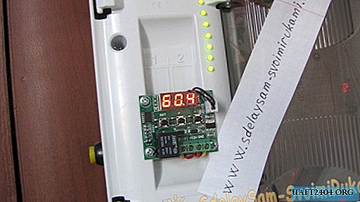
After collecting the parts, you need to think about placing the parts on the board. I did, as in the photo, and you are free to arrange them to your liking. The main thing is that the location of the parts meets the objectives of reducing the number of jumpers and soldering, and most importantly ease of use. Accuracy in assembling the circuit is not the last thing, no need to rush like me and everything will be beautiful. So let's get started.


The power of the water level indicator in the tank can be made from any 12 volt battery (even an old one, if only it would give no less than 10 volts), for example, from a computer uninterruptible power supply, and now they are sold a lot of all kinds of low-power ones. Or you can use ordinary batteries in the country. If they are connected in series 8 pieces of 1.5 volts = 12 volts. Quite enough. And if you connect the batteries through the button, so that the circuit works only when the button is pressed, then this power will last for many years.
It remains only to test the water level indicator in the tank and the main thing here is not to confuse the plus with the minus. Power wires are better to connect different colors. Plus is always indicated in red, and minus black, if you get used to it, you will not mistake it.
Share
Pin
Tweet
Send
Share
Send