Share
Pin
Tweet
Send
Share
Send
I decided to make my contribution to such devices. More precisely, I came up with an actuator. They, in turn, can include a solenoid. This device can be used to turn on lighting or something else.
The design is very simple. You can repeat it without any problems.
Details and materials
For the construction you will need:
- - RG45 socket;
- - cable connector RG45;
- - 12 volt relay;
- - battery;
- - wires, soldering iron.
Making simple protection
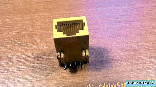
I have a socket from an old router, dropped out on occasion. You can buy in China or drop out of the old motherboard. Later I thought that it was necessary to drop out from the motherboard, there are also LEDs (they would be useful for indicating the operating mode).
I bit the cable connector off the old cable. You can compress a new one, but I had an old wire lying around, so I took it. And as an example of accessibility, not everyone has a cable crimping tool. In total, they need two pieces. The wire from the router is probably not a problem to get.

Relay removed from the old board. Initially, the circuit was designed for a bipolar relay.
But access turned out to be unipolar. Not fundamentally. I will indicate in more detail below.

The scheme is simple. Jumpers in the main unit and jumpers in the key can be closed in random order. The diagram shows the contacts of a bipolar relay. But since I have one pole, the jumper of one group is indicated in the circuit.

On the key we close the wires according to the diagram. If you take the connector with wires to you and the key down, then the contact report is from right to left. We protect the wires and temporarily twist. We bite off the extra wires.

The actuator is assembled in a single design. Do not forget about the jumpers and the wire going to the second pin of the RG45 connector. We connect the power.

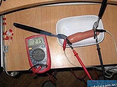
We are testing. In the role of a controlled device, I used an LED light bulb.

Now we simulate an emergency power outage, the battery is dead or the power is turned off. We solder the wires from the battery. Why do we need a wire going to the second pin of the connector? With it, we apply a plus from an external device to our relay.

We take the second cable connector RG45. Temporarily solder to the battery, which was used to power the main device. As was shown in the diagram, we close the contacts 1 and 8 and solder them out to minus. The second contact is soldered to the plus of the battery.
This key also serves as a master key for us and is used in an emergency.

Just insert it into the socket, the relay is activated and turns on the light bulb. Well, or in real life it unlocks the door lock of the guarded room, for example.

The wires of the key are soldered, isolated. We make a loop of wire and seated with a heat shrink tube.

Such an executive device turned out. This is just the basis of the design, where and how to apply it to everyone who collects it. For me it will serve to unlock the door in the workshop.
Watch the video of the work and manufacture of the device
Share
Pin
Tweet
Send
Share
Send