Share
Pin
Tweet
Send
Share
Send
It's about a flashlight that works without batteries. Perhaps someone already saw the simplest Faraday generator on the Internet, which allows you to light a small LED from several movements of the conductor in the winding. Assemblies from an almost dead battery, an autotransformer and a transistor, which are capable of supplying a 3V LED at an initial voltage of tenths of a volt are also not uncommon.
Here, the author went a little further by upgrading the device circuit, adding a rectifier, supercapacitor (ionistor), resistance, and completely eliminating the power source. As a result, the work of the flashlight has become much more stable and efficient. And if the case is shaken for several minutes, it can be charged for a long time of operation of the LED. How it works? Let's get it right.
Principle of operation
The device consists of several inductors, which you can assemble yourself. The primary inductor actually serves as a power source or completely replaces its familiar counterpart - a battery. Due to the movement of a rod of permanent magnets in it, an electric current is induced. Due to oscillatory movements in a magnetic field, electric waves are generated, emanating from the coil with a certain frequency. Rectifier or diode bridge helps to stabilize them and convert to direct current.
Without the storage capacity, such a device would have to be constantly shaken, therefore, the next element in the circuit is a supercapacitor, capable of recharging by the type of battery. Next, a step-up transformer or voltage converter is connected, which consists of a toroidal ferrite coil and two windings - the base and collector. The number of turns may be the same, and is usually 20-50. The transformer has a midpoint connection at the opposite ends of both windings, and three outputs to the transistor. The autotransformer increases the meager current pulses to sufficient for the LED to work, and a bipolar transistor is connected to control them. A similar electrical circuit has different names in different sources: a thief of joules, a blocking generator, a Faraday generator, etc.


The necessary resource base for homemade
Materials:
- PVC pipe, diameter 20 mm;
- Copper wire, diameter - 0.5 mm;
- Low power reverse conductivity transistor;
- Neodymium magnets round, size 15x3 mm;
- Diode bridge or rectifier 2W10;
- Resistor;
- Supercapacitor or Ionistor 1F 5.5V
- Button switch;
- LED white or blue at 5V;
- Transparent adhesive type epoxy;
- Hot glue;
- Pieces of plywood, cotton;
- Copper wiring in isolation.
Instruments:
- Soldering iron;
- Hot glue gun;
- Hacksaw for metal;
- File, sandpaper.
Flashlight manufacturing process
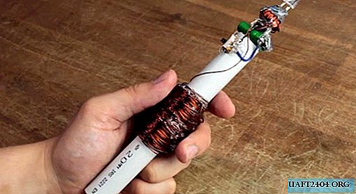
The flashlight body will be made of PVC pipe. We mark a segment 16 cm long, and cut it with a hacksaw for metal.


From the center of the segment mark 1.5 cm in each direction. It turns out a zone for a winding 3 cm wide.


Next, we take a copper wire with a cross section of 0.5 mm, leave one end of it about 10-15 cm long, and wind the wire onto the tube-body of the flashlight according to the manual marking. It will be necessary to wind quite a lot, more than five hundred turns. The first few of them can be fixed with glue. The initial row of the coil is tightly pressed against each other, and we make it strictly consistent.


At maximum points, the winding should be approximately half a centimeter thick. We clean both ends of the wire with sandpaper for reliable adhesion.


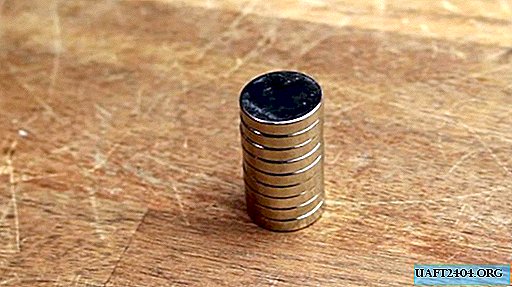
The moving magnetic core of the coil can be either integral or assembled in parts. Neodymium magnets are selected according to the inner diameter of the PVC tube. The necessary length of the magnetic rod is experimentally gained, through the oscillations of which an electric current will be created.


The author used ten magnets with a thickness of 3 mm to gain the maximum rational length for such vibrations, and at the same time equal to the width of the winding.
 center
On the scale of the oscilloscope, you can see the difference between the potentials obtained from the oscillations of one and ten magnets. The author received a voltage of 4.5V from oscillations of the magnetic rod. It also clearly shows the cyclicity of the sine wave in the intervals of varying frequency.


At this stage, according to the example of the author, it is possible to connect an LED directly to the outgoing ends of the coil, and check its operability. As can be seen in the photo, the LED responds to the movement of the magnetic rod, and the pulse current created by it itself.


Now you need to muffle both ends of the tube so as not to hold them with your hands while shaking. To do this, use the same hacksaw to cut out a few spots from the plywood, process the edges with a file, lay a cotton swab on the back to soften and put them on glue so that they do not fall out.


It was the turn to connect the rectifier. The diagram shown in the photo shows which two of its four contacts out of four are connected to the coil. Such a diode bridge is able to receive alternating current, and give a constant strictly in one direction.


The step-up autotransformer will help to convert low spontaneous pulses from the primary coil to sufficient voltage for the LED to work due to self-induction of one of the windings - collector. Since it is connected to the base winding, a constant and stable electric current will be supplied to the supercapacitor in sufficient quantity. The resistor will limit the excess of permissible values. A capacitor of sufficient capacity is also selected experimentally by the author using measurements of outgoing signals by an oscilloscope.


This circuit is closed by a bipolar transistor of reverse conductivity, which controls the incoming electric current to the LED. You can assemble the circuit without a board, since there are not so many parts. We install the switch button on one of the contacts coming from the autotransformer.


The author preferred to assemble his improvised flashlight design on hot glue, while improving the insulation of contact groups. The switch button is located on the side of the flashlight. However, the author pasted the main elements of the circuit on one another from one of the ends. The LED remains the locking element, which can be ennobled with protective glass or a reflector.


Despite the unpretentious appearance of the device, suitable only for laboratory-experimental home-made work, such a flashlight is quite functional and, if necessary, will not allow the darkness to disappear. To assemble such a scheme is not difficult at home and at minimal cost. And the complete lack of batteries makes it a truly useful device for various emergencies.


Share
Pin
Tweet
Send
Share
Send