Share
Pin
Tweet
Send
Share
Send
Good day, dear readers! Today we will focus on the assembly of a simple low-pass filter. But despite its simplicity, the filter is not inferior in quality to store analogues. So let's get started!
Key Filter Features
- Cutoff frequency 300 Hz, higher frequencies cut off;
- Supply voltage 9-30 Volts;
- Consumes a 7 mA filter.
Scheme
The filter scheme is shown in the following figure:

Parts List:
- DD1 - BA4558;
- VD1 - D814B;
- C1, C2 - 10 uF;
- C3 - 0.033 uF;
- C4 - 220 nF;
- C5 - 100 nF;
- C6 - 100 uF;
- C7 - 10 uF;
- C8 - 100 nF;
- R1, R2 - 15 kOhm;
- R3, R4 - 100 kOhm;
- R5 - 47 kOhm;
- R6, R7 - 10 kOhm;
- R8 - 1 kOhm;
- R9 - 100 kOhm - variable;
- R10 - 100 kOhm;
- R11 - 2 kOhm.
Making a low pass filter
On the resistor R11, capacitor C6 and Zener diode VD1, a voltage stabilization unit is assembled.

If the supply voltage is less than 15 volts, then R11 should be excluded.
On the components R1, R2, C1, C2 an adder of input signals is assembled.

It can be excluded if a mono signal is input. The signal source should be connected directly to the second pin of the chip.
DD1.1 amplifies the input signal, and on DD1.2 the filter itself is assembled directly.

Capacitor C7 filters the output signal, a sound control is implemented on R9, R10, C8, it can also be excluded and the signal can be removed from the negative leg of C7.
We figured out the circuit, now let's move on to the manufacture of a printed circuit board. For this we need fiberglass with dimensions of 2x4 cm.
Low Pass Filter Board File:
plata.zip 25.04 Kb (downloads: 447)

Grind to a shine with fine-grained emery paper, degrease the surface with alcohol. We print this picture, transfer it to the textolite using the LUT method.


If necessary, paint the tracks with varnish.
Now you should prepare a solution for etching: dissolve 1 part of citric acid in three parts of hydrogen peroxide (1: 3 ratio, respectively). Add a pinch of salt to the solution, it is a catalyst and is not involved in the etching process.
Immerse the board in the prepared solution. We are waiting for the dissolution of excess copper from its surface. At the end of the etching process, we take out our board, rinse with running water and remove the toner with acetone.

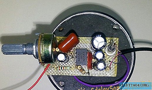
Solder the components, focusing on this photo:

In the first version of the picture, I did not make a hole for R4, so I soldered it from the bottom, this drawback was fixed in the download document.
On the back of the board you need to solder the jumper:

The assembled circuit worked at the first start-up and does not need to be configured. If there is no sound at the output, turn the variable resistor and check all the connections on the board.
This concludes my article. Good luck to everyone in the repetition!
A few photos of the finished product:


Share
Pin
Tweet
Send
Share
Send