Share
Pin
Tweet
Send
Share
Send
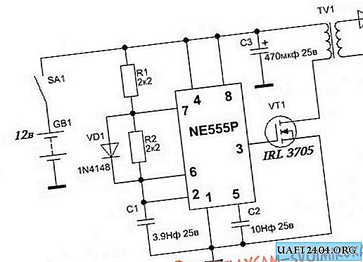
The power of such a converter largely depends on the field effect transistor used. The main types of field effect transistors used are IRFZ44, IRL3705, IRF3205. The last two work fine, but on the first you can observe a lot of heat, although the transistor needs a heat sink.
The power of the converter directly depends on the power source, with an uninterruptible battery power of about 50-60 watts or more.
Such a converter will be able to charge a capacity of 400 volts 1000mkF in just one second! and all this thanks to the increased power of the converter.


As you know, the 555 series microcircuit can work in two modes - 1) as a timer (the main purpose of the microcircuit), 2) as a rectangular pulse generator, in our case, the microcircuit works as a master oscillator.
The pulses that the microcircuit produces go to the gate of a powerful field-effect transistor, as a result of which it forces it to open and close at a given frequency (frequency of the generated pulses), forming an alternating voltage of high frequency in the primary winding of the transformer.


The primary winding of the transformer consists of 7 turns of 1 mm wire, you can also use several cores of a thinner wire, for convenient winding.

Next, we put insulation on top of the primary winding and wind the secondary one. The winding consists of 120 turns of wire with a diameter of 0.2-0.3 mm.
The winding is wound in layers, each layer of 40 turns. As interlayer insulation, you can use adhesive tape, insulation tape, fluoroplastic, etc.

The power of the converter is quite high, so the circuit can be used as a converter of 12-220 volts, but in this case the number of turns in the secondary winding must be reduced to 65.


The transformer can be wound on a ferrite ring, an armored cup or a W-shaped frame (ferrite), the dimensions are not very important, the main thing is that the windings fit.


In my case, the installation is done on a breadboard from two sides. SMD components were also used to reduce board sizes. The transformer was also mounted on the board.


The output voltage of the converter is about 380-440 volts, for rectification you can use any pulse diodes with a voltage of 1000 volts and a current of at least 1 ampere (FR107, FR207, UF4007 and others).

Share
Pin
Tweet
Send
Share
Send