Share
Pin
Tweet
Send
Share
Send
The article will focus on one of the most common applications of the NE555 - a dimmer for adjusting the brightness of LEDs, which can be adapted for a makeshift nightlight.
Part 1. Electronics.
The device diagram is presented below: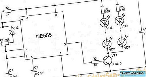
Diodes VD1 and VD2 can be taken any, for example 1N4148. R1 adjusts the brightness of the VD3-VD9 LEDs. A variable resistor can be taken combined with a switch, this option will look good in styling under old kerosene lamps, in which the brightness of the flame was controlled by a special pen. If you do not plan to change the brightness of the lamp, then any tuning resistor set to a suitable value will do. Capacitor C3 may be of a smaller nominal value, or it may not exist at all - the circuit will still start, however, in this case, the dimmer will emit a barely audible squeak.
Board Assembly:


LEDs are divided into two groups of 4 and 3 LEDs. They, of course, can be more or less, but you need to remember that the choice of transistor VT1 depends on the number and power of the LEDs. For a small number of low-power LEDs, like mine, any NPN transistor, even KT315 or its foreign analogues, is suitable. For a more “gluttonous” load (for example, LED strip and high-power LEDs), it is better to choose a transistor type EB13005, which can be found in any energy-saving lamp, or the widespread field effect transistor IRFZ44N.
The NE555 has a wide supply voltage range, so any suitable power supply (such as a laptop) or charging from a telephone can be used for the circuit. It is not recommended to power the dimmer from batteries or accumulators, since the switching circuit of LEDs with limit resistors does not imply a sufficiently high efficiency, and the power source is quickly discharged.
The number of LEDs and the resistance of their current-limiting resistors will depend on the voltage. If you know how it is calculated, feel free to move on to the next part; if not, spend a couple of minutes reading the short manual.
So, the resistance is calculated by the formula:
R = Upit - Usb / Isv, where
R is the resistance of the current-limiting resistor;
Upit is the supply voltage of the circuit;
Usb - voltage drop on the LED;
Isv is the power supply current of the LED.
The values of Usv and Isv differ depending on the color and power of the LEDs, it should be clarified in the documentation for a specific model. If there is no documentation (which is the norm for the vast majority of Chinese products), then you can use the averaged values from the table:
Color and type | LED voltage drop (volt) | LED supply current (amps) |
Red 5 mm. | 1.8-2.1 | 0.02 |
Yellow 5 mm. | 1.9-2.3 | 0.02 |
Blue 5 mm. | 2.5-3.5 | 0.02 |
Green 5 mm. | 2.5-3.5 | 0.02 |
White 5 mm. | 2.5-3.5 | 0.02, 0.05-0.07** |
White 1 W * | 3.2-3.4 | 0.3 |
White 3 W * | 3.2-3.4 | 0.7 |
* For LEDs of 1 Watt or more, a heat sink is required for cooling.
** A current of 0.05-0.07 A is required for superbright white LEDs.
The parameters presented in the table are approximate. So, for example, for 5-mm LEDs, the supply current can vary in a fairly wide range - from 5 to 35 mA, however, with a minimum value, they will glow dimly, and at maximum, they will quickly overheat and fail.
Now we use the above formula and calculate the resistance of the resistor for a chain of four series-connected LEDs: three yellow and one white. Let the supply voltage of the circuit be 12 volts.
To begin with, we find out the voltage drop across the entire chain using the formula
Usb = U1 + U2 + ... + Un, where
U1, U2, Un - voltage drop on each LED of the chain.
Usb = 1.9 + 1.9 + 1.9 + 2.5 = 8.2 volts.
Current in series connection does not change, that is, on all elements of the circuit its value will be 0.02 A.
We proceed to the calculation of resistance:
R = 12 - 8.2 / 0.02 = 3.8 / 0.02 = 190 Ohms.
We select a resistor from the standard line that is close to the result - 200 Ohms.
At the same time, it would be nice to calculate the minimum power of the resistor:
P = (Upit - Usb) * Isv
P = (12 - 8.2) * 0.02 = 3.8 * 0.02 = 0.076 W
The closest one in power is 0.125 W, but you can choose with a margin of 0.25 W.
The resistor can be of greater resistance (within reasonable limits). When assembling the circuit, I did not find a 300 Ohm resistor and replaced it with 470 Ohm, limiting the current to 0.015 A. Due to the fact that the current / brightness ratio of the LEDs is non-linear, this replacement did not affect the final result.
Now you know how to independently calculate the values suitable for your needs. Combining different colors, you can get beautiful combinations and shades that will make the nightlight more “magical”. So the combination of orange and warm white gives a nice peach color, and yellow and green will turn out a soft color of the “green lawn”.
Part 2. Appearance.
As you know, the assembled and working board is only half the device. The design is no less important, and problems often arise with it. It’s good if you have a suitable case from some Chinese night lamp for $ 1, but if not, do not despair, simple and original solutions can be found in the most unexpected place. For example, in the bathroom.So, we need:
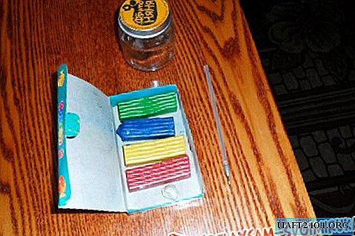
1. Empty plastic can (for example, from a hair conditioner) - 1 pc.
2. Lids from this and another same can - 2 pcs.
3. Matte self-adhesive with a pattern.
4. A piece of sandpaper.
5. Nail polish remover or acetone.

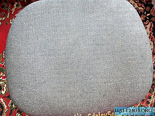
1. We release the jar from the glued paper. Using nail polish remover, remove glue residue. Do not forget to ventilate the room well! Having got rid of the glue, we wash the jar with warm water and soap and dry it.
2. Using a fine skin, we mat the surface of the can. We cut off a piece of self-adhesive of suitable length and width, glue it around the jar with a circle. Choose a picture that will scatter light well and beautifully.
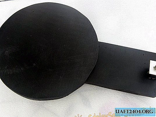
3. Now glue one lid to the bottom of the can - this will be the “bottom” of the lamp. You can pre-paint the lids from the spray can, or you can leave it as is - then they will be illuminated by LEDs, creating an additional effect.

4. In the second cover, we drill a hole for the power wire (and, if necessary, for a variable resistor). Their location depends on the chosen design: in a pendant lamp, the hole for the wire is better located in the center of the lid, in a table - on the side. In addition, in the desktop version, it is more convenient to place the board at the bottom of the lamp, that is, the glued “bottom” will be on top, and the screwed cover with the board inside will be at the bottom, since the wire imperceptibly lying on the table looks more aesthetic than hanging from somewhere above. Pass the wire through the hole and solder it to the board. Do not forget also about the connector for connecting to the power supply and the switch, they can be made mounted. The board itself can be fixed on the back of the cover with silicone glue.
download board
5. We fasten the top cover.

It remains only to build some kind of fixture, if you plan to make the nightlight suspended.
The lamp is ready!

Share
Pin
Tweet
Send
Share
Send