Share
Pin
Tweet
Send
Share
Send
The antenna amplifier below is extremely easy to manufacture. It has good gain, low noise and low current consumption. Plus a very wide range of work. Yes, also a miniature size, thanks to which it can be embedded anywhere.
Where can I use a universal antenna amplifier?
Yes, almost anywhere in a wide range of 50 MHz - 4000 MHz.
- - As a signal amplifier of a television antenna for receiving both digital and analogue channels.
- - Like an antenna amplifier for an FM receiver.
- - others
This is for domestic use, but in the amateur field of application, much more.
Antenna amplifier specifications
- Operating range: 50 MHz - 4000 MHz.
- Gain: 22.8 dB - 144 MHz, 20.5 dB - 432 MHz, 12.1 dB - 1296 MHz.
- Noise figure: 0.6 dB - 144 MHz, 0.65 dB - 432 MHz, 0.8 dB - 1296 MHz.
- Current consumption is about 25 mA.
More detailed specifications can be found in datasheet SPF5043Z.
The low-noise amplifier has proven itself perfectly. Low current consumption justifies itself.
The chip also withstands high-frequency overloads without loss of performance.
Production of antenna amplifier
Scheme
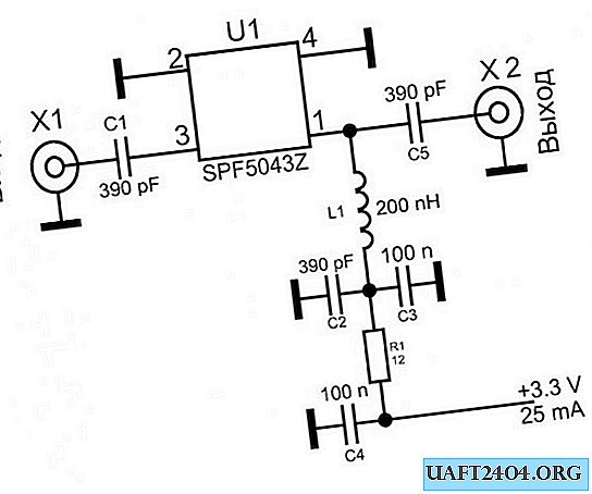
The circuit uses a RFMD chip SPF5043Z, which can be purchased at - Ali Express.
In fact, the whole circuit is an amplifier microcircuit and a filter for its power supply.
Amplifier board

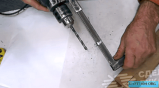
The circuit board can be made of foil PCB, even without etching, as I did.
We take two-sided foil textolite and cut out a rectangle about 15x20 mm in size.

Then, with a permanent marker, draw the wiring along the ruler.


And then you want to poison, but want to cut the tracks mechanically.
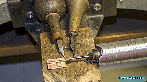
Next, we tin everything with a soldering iron and solder SMD elements of size 0603. We close the bottom side of the foil board to a common wire, thereby screening the substrate.


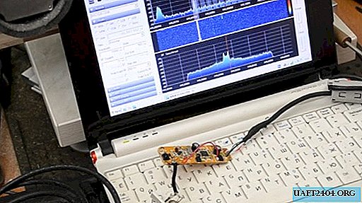
Tuning and testing
Tincture is not required, you can of course measure the input voltage, which should be within 3.3 V and the current consumption is approximately equal to 25 mA. Also, if you work in the range above 1 GHz, then you may need to coordinate the input circuit by reducing the capacitor to 9 pF.
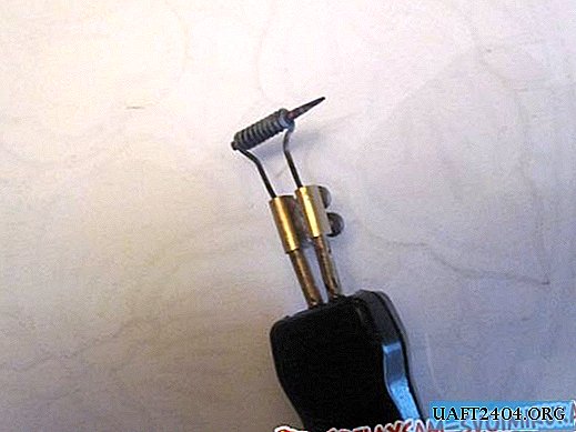
We connect the board to the antenna. The test showed good gain and low noise.
It will be very good if you place the board in a shielded case, such as this.

The board of a ready-made amplifier can be bought at AliExpressBut it costs several times more than a microcircuit separately. So it’s better to get confused as it seems to me.

Scheme Addition
To power the circuit, a voltage of 3.3 V is required. This is not very convenient, for example, if you use an amplifier in a car with a voltage of 12 V.

For these purposes, you can enter a stabilizer in the circuit.
Connecting an amplifier to an antenna
By location, the amplifier should be located in close proximity to the antenna.
To protect against static and thunderstorms, it is desirable that the antenna be closed by direct current, that is, you need to use a loop or frame vibrator. A Biquadrat antenna would be a great option.
Watch a simple amplifier test video for the antenna
Share
Pin
Tweet
Send
Share
Send