Share
Pin
Tweet
Send
Share
Send
The most important part in the boron machine, of course, is the electric motor. The engine for an average in price and quality boron machine should produce about 16-18 thousand revolutions per minute. This is quite enough to process wooden billets and crafts, bone, plastic, aluminum and duralumin, as well as suitable for processing non-solid minerals and stones. Engines from 20 thousand revolutions per minute are already capable of working with solid minerals and metals ... It so happened that I got a working engine from a toy motor boat on a remote control, which I was given for spare parts. Repairing this toy did not seem cost-effective; electronics burned out due to water was a little cheaper than the toy itself. However, its engine itself was not injured. The engine there stood at 9 volts, quite large, powerful and quite resourceful - it is understandable, it is put in a toy to quickly push it through the water, and for this purpose the motor must be powerful and resourceful.

Unfortunately, I don’t have a device for measuring revolutions, but it felt like trying to stop the shaft of a working engine with my fingers, it became clear that it can be used to make a simple boron machine, which, at least for working with wood, plastic and bone definitely fit.
Will need
- The engine from a toy boat (or similar, the same characteristics - 9-12 volts).
- A suitable voltage power supply or adapter to power the motor.
- Plug, and connector to it.
- Start button.
- Pipe, with an inner diameter under the engine, and in length, see 15-17.
- Plastic sheet, 2-3 mm thick. (for the ends).
- Second glue and soda.
- Miniature collet chuck with 3.17 mm connector. and clamp from 0.3 to 3.5 mm.
- Any copper insulated wires.
Tool required for work:
- Soldering iron with tin and flux.
- File.
- Sandpaper, medium grit.
- A knife with a strong and sharp blade (preferably a technical scalpel).
- Emery machine or burner (for cutting plastic).
Making boron cars
First you need to check the motor itself - it should work evenly, without emitting odors, not heating up immediately when connected. You can try on a cartridge.

In the future, a little heating during operation is normal. Also, with the help of the battery and the LED, you can check the start button and the plug with its connector for functionality; it is better to identify and eliminate the malfunction at the beginning of assembly than at the end. Since the machine we plan is simple, without any speed switches, the start button can be taken the simplest, one-stroke, like a key on, say, a remote control. I.e; pressed - it works, released - it stopped working. It’s also safe; in an unforeseen, undesirable situation, we ourselves, involuntarily, remove the finger from the button, thereby avoiding possible injuries or damage to surrounding objects. The plug with the connector can be chosen at your discretion, the main thing is that they fit together and be workers.

So, we take a pipe of suitable (or approximately suitable!) Diameter. I cut a piece of pipe from an old, unnecessary vacuum cleaner. We try on an engine in it. If the pipe is a little too big - it’s not scary (the main thing is not small!), Just wind several turns of insulation tape on the engine so that it becomes a suitable gauge. In addition, a soft and flexible electrical tape will act as a kind of shock absorber - it will dampen and absorb vibrations that inevitably form when the engine is running. If the pipe and the engine come together, let's deal with the ends. To do this, measure the width of the place of the engine with which we will attach it to the end, drill a suitable hole in the plastic sheet and insert the engine into it. It turns out like this:

Next, insert the engine into the pipe until the plastic sheet rests against the end. We draw a marker around the contour.

We remove the sheet from the engine and with the help of a burner or an emery machine, cut a round end wall along the contours. We also do the rear end.


Only here the situation is simpler - here it is not necessary to calculate the center, where to make a hole for the plug connector. We measure the width of the connector, and drill a suitable hole approximately in the middle of the finished end plate. Now let's deal with the button. We will choose the most convenient place for ourselves where it will be located. We measure the parameters of the button, and transfer them to the selected location.

We cut (or drill) a suitable hole.


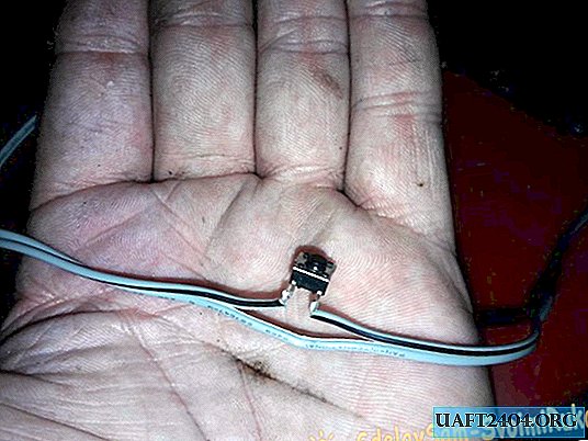
Next, take a double copper wire, see. 20 long.

We determine its middle, in this middle we cut one of the cores in half, solder the cut-off core in the middle to the contacts of the button. It turned out a two-wire wire, with a breaker in the middle on one of the cores. Here is one:
Now we pass the wire with the button into the pipe, find the hole for it with the button and insert the button into this hole from the inside. We fix it with second glue.

Only carefully so that the glue does not get into the button mechanism. Then we solder the front ends of the wire to the motor contacts. We attach the end plate to the engine with glue.

Coat the ends of the pipe with glue and insert the engine with the plate into the pipe until the end plate rests against the ends of the pipe coated with glue. Press firmly for 10-15 seconds until the glue sets.

In the same way, we attach the rear end, not forgetting to glue the plug connector to it with the ends of the wire soldered to it.


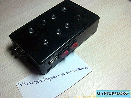
The main work is completed.

Now, using a file and an emery cloth, we even out the corners of the ends so that they are flush with the walls of the case.

Next, install the plug from our connector on the wire of the power supply.


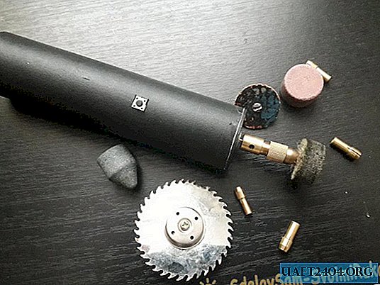
Do not forget about the polarity. If you mix it up, it’s okay, in principle, it won’t happen, it’s just that the shaft will turn in the wrong direction and, naturally, we won’t be able to drill anything. However, if you plan to use this device only for cutting small objects, or sharpening knives, then the polarity does not play a special role. It remains to install only the collet chuck on the shaft, and you can use it. A collet chuck, diamond feathers for a bor machine, and thin drills I ordered in an online store.

Unfortunately, so far only a cartridge has come, so I was able to demonstrate on the video only the cutting and sharpening properties of the assembled device. And then, with homemade nozzle files. Sharpen metal, grind, and cut plastic, it is quite peppy, which means that drilling will be good.
Share
Pin
Tweet
Send
Share
Send