Share
Pin
Tweet
Send
Share
Send
As you know, the first transistors that replaced the radio tubes were precisely germanium. Their invention played a large role in the development of electronics, making electronic devices more functional, economical and small-sized. However, the era of germanium transistors did not last long - soon they were replaced by more advanced silicon ones. Despite this, a huge number of germanium transistors were produced, and even now, after half a century, they are not very rare.
There is an opinion that the sound of an amplifier built entirely on germanium transistors has a special color, close to the "warm tube" sound. This is exactly what makes germanium transistors so popular in the ham environment recently. You can listen with your own ears to the sound of such an amplifier, if you assemble a very simple circuit shown below.
Amplifier circuit

The circuit consists of 5 germanium transistors and a small handful of other parts. Below are several options for transistors for this circuit.
- T1 - MP39, MP14, MP41, MP42 (PNP)
- T2, T4 - P217, P213, P210, P605, GT403 (PNP)
- T3 - MP38, MP35, MP36 (NPN)
- T4 - MP39, MP14, MP41, MP42 (PNP)
Any other similar transistors are also suitable, low-noise are most preferred. It should be noted that in the output stage (T2 and T4) there should be identical transistors, it is advisable to pick them up in a pair at the closest gain. The diode D1 is germanium, for example, D9, D18, D311, the quiescent current of the amplifier depends on it. All capacitors are electrolytic, for a voltage of at least 16 volts. The supply voltage of the circuit is 9-12 volts.
Printed circuit board:
usilitel-na-germanievyh-tranzistorah.zip 12.92 Kb (downloads: 565)

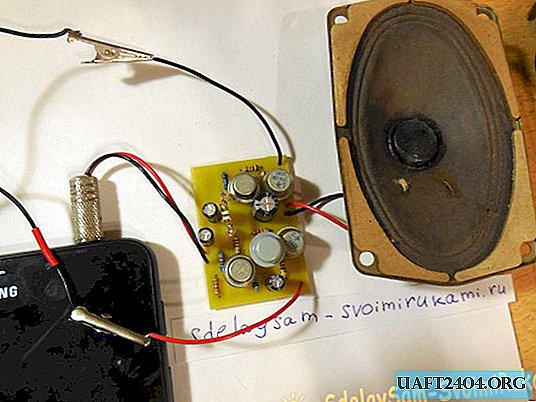
Amplifier assembly
The circuit is assembled on a 40x50 mm board, which can be performed using the LUT method. Below are photos of the finished tinned board.


Now you are ready to install the parts. First of all, resistors get on the board, after them larger capacitors and transistors. It should be borne in mind that germanium transistors, unlike silicon transistors, are much more sensitive to overheating.

Powerful output transistors heat up during operation at high volume, so it is advisable to install them on a radiator (if the transistor case provides such an opportunity) and put them on the board with wires.

After installing all the parts on the board, it remains to solder the power wires, signal source and speaker output. The final stage of assembly is to wash off the flux residues from the board, check the installation, ring adjacent tracks for a short circuit.
First power up and setup
The germanium amplifier requires the setting of the quiescent current, which is set by the diode D1. First of all, you need to apply voltage to the circuit, including an ammeter in the gap of the supply wire. If there is no signal at the input, the circuit should consume about 20-50 mA. The larger the quiescent current, the greater the heating of the output transistors, however, this positively affects the sound quality. If the quiescent current is too small, the sound becomes illegible, a rattle and hoarseness appears. The current can be increased by adding one or more diodes in series with D1. In my case, to get an acceptable sound quality I had to add two additional diodes.
Similar circuits of amplifiers based on germanium transistors were widely used in old turntables, tape recorders, radios, so it will surely appeal to all lovers of antiquity. The output power is about 5-10 watts with a radiator, so an amplifier with a head is enough to sound an entire room. Have a nice build!
Share
Pin
Tweet
Send
Share
Send