Share
Pin
Tweet
Send
Share
Send
Power supply circuit

For assembly we need
- Voltage stabilizer LM317 (3 pcs.)
- 100 ohm resistor.
- Potentiometer 1 kOhm.
- Electrolytic capacitor 10 uF.
- Ceramic capacitor 100 nF (2 pcs.).
- Electrolytic capacitor 2200 uF.
- Diode 1N400X (1N4001, 1N4002 ...).
- Heatsink for microchips.

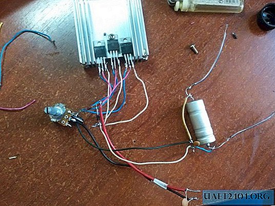
Circuit assembly
We will assemble the circuit by hinged installation, since there are few details. First, we attach the chips to the radiator, and it will be more convenient to assemble. By the way, it is not necessary to use three LMs. They are all connected in parallel, so you can do two or one. Now we solder all the leftmost legs to the leg of the potentiometer. Solder the plus of the capacitor to this leg, minus the solder to the other output. So that the capacitor does not interfere, I soldered it from the bottom of the potentiometer.

To the potentiometer leg, to which the left legs of the microcircuits are soldered, we also solder a 100 Ohm resistor. We solder the middle legs of the microcircuits to the other end of the potentiometer (I have purple wires).

We solder a diode to this resistor leg. We solder all the right legs of the microcircuit to the other leg of the diode (I have white wires). Plus solder one wire, it will be a plus of the input.

We solder two wires to the second output of the potentiometer (they are black for me). This will be minus entry and exit. We also solder the wire (I have it red) to the resistor where the diode was previously soldered. This will be a plus exit.

Now it remains to solder to the plus and minus of the input, the plus and minus of the output along the capacitor at 100 nF (100 nF = 0.1 μF, marking 104).

Following the input, we solder the capacitor at 2200 μF, the positive leg is soldered to the plus of the input.

At this point, the manufacture of the circuit is ready.

Since the circuit produces 4.5 amperes and up to 12 volts, the input voltage should be at least the same. The potentiometer will already regulate the output voltage. For convenience, I advise you to put at least a voltmeter. I will not do the full body, all I did was attach the radiator to the fiberboard segment and screw the potentiometer. I also pulled out the output wires and screwed crocodiles to them. This is quite convenient. Next, I attached it all to the table.


Share
Pin
Tweet
Send
Share
Send